


Using the Water Table Reflection to Add Topography
The interface from drier to wetter soils represents a very large change in electrical properties. The reflection from this interface can be one of the strongest interfaces seen with GPR. Water and air represent the most extreme relative dielectric constant (K) values for commonly occurring materials:
Kwater= 80 and Kair = 1.
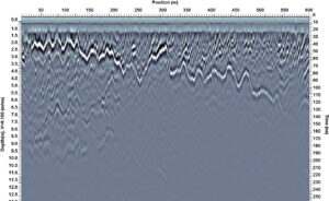
Dry sediments with air in the pore space has a low bulk dielectric permittivity of about 5. Below the water table, the air is replaced by water in the pore space so the bulk dielectric permittivity is much higher; typically around 20 to 30. Reflection strength depends on the difference between material permittivities, so the strong water table reflection amplitude often dominates the GPR reflection section as shown in this image.
Given that the water table provides a strong, easily interpretable reflector and if we assume the water table is a flat, horizontal boundary (which it usually is) the depth of the water table on the GPR section mimics the elevation change along the GPR profile line. Extracting the depth of the water table along a GPR line provides a means to compensate the GPR section for the topography.
The EKKO_Project Interpretation module is ideally suited for this task. Adding a ‘polyline’ interpretation along the water table reflector provides depth to the water table reflector which are extracted to a spreadsheet . The “Position” and “Depth” columns (shown in green) are extracted and saved as a topography (.top) file and attached to the GPR line. Topography files are special “positioning” files that EKKO_Project recognizes and are used to automatically interpolate an elevation value for every GPR trace in the GPR line.

Elevation information allows the GPR line to be plotted with an elevation axis in the LineView module. Correcting a GPR line for the topography provides a more representative image for further interpretations about the structures imaged by the GPR.

A strong GPR reflector is not always the water table and ground truth should be sought to confirm it. In addition, the water table is usually gradational and is not always visible when the GPR pulse length is similar or shorter than the gradation width (in other words, if the GPR frequency is high, the water table may not be visible in the GPR cross section). Since it does not take long to flatten a selected reflector using EKKO_Project, experimenting to see if reflector topography makes the subsurface structures and stratigraphy more understable can be done on a trial and error basis.
In this example, the GPR line started on the beach at the shoreline, essentially right on top of the water table, and ran perpendicular to the Lake Superior shoreline. A strong reflector gets deeper as the GPR line moves higher in elevation up the beach; it is pretty easy to confidently interpret this reflector as the water table. Flattening the GPR line on the water table reflector corrects the orientation of other reflectors; these show lakeward-inclined strand-plain structures with progradational and stillstand sequences. Interpreting these structures helps to better understand how Lake Superior shorelines have developed during a period of lake level drop.
See this video link of how to add a topographic correction to your GPR data using the EKKO_Project software: https://youtu.be/M_4-m9uswhA?t=1879
Data courtesy of Dr. Harry Jol, University of Wisconsin, Eau Claire


